The following information has been prepared as a guide for architects, building department officials, engineers, health agencies, plumbing contractors, and others concerned with high standards of sanitation and construction.
GENERAL INFORMATION
A grease separator is a device designed and installed in the drain line to separate and retain various destructive, hazardous and other undesirable matter from waterborne waste so that they may be periodically removed; thus preventing their passage into the drainage system. Preventing grease from entering the sewer system (which results in clogging of laterals, mains and disposal difficulties at treatment plants) can be accomplished by the installation of efficient grease separators at the source of the grease.
SOME MAJOR POINTS WHERE GREASES ENTER THE SEWER SYSTEMS ARE:
- Restaurants, cafeterias, hotels, hospitals and establishments with kitchen facilities.
- Drains from soup kettles, stock kettles, meat, fish or fowl preparationin commercial facilities.
- Animal slaughtering facilities, fowl, fish or meat packing establishments.
When grease in large quantities enters the drainage system, it often causes clogging of house or building drains and sewers, resulting in poor fixture operation and the possibility of basement flooding during peak flows. Cleaning of such drains and sewers is inconvenient and expensive.
Large quantities of grease in sewage constitute serious nuisances and cause many difficulties in sewage treatment and disposal. Grease-laden wastes mix with cold sewage in the mains, causing the grease to congeal and adhere to the solids. By the time the sewage has reached the treatment plant, a thorough mixing of grease and solids has occurred. Since bacterial action on grease is slow, it does not decompose readily and is carried through the plant, affecting the operations at many points, depending on the type of treatment.
Small amounts of grease adhering to grit and to the heaviest solids are removed in the grit chambers, where the sewage enters the disposal plant. Some plants have special separators designed to remove grease by flotation, separating it from solids by injecting air into the sewage, but this is only partially effective.
In settling basins used for the removal of solids, the greatest difficulty with grease is encountered. Some solids are carried to the top of the grease and decompose in contact with the air, giving off disagreeable odors. Others are held in suspension by the grease and are carried beyond the settling basins. Grease is also carried down with heavy solids to the bottom, thereby retarding normal bacterial action. When entering the digestion tanks, rising grease forms a scum on the surface, retarding the liberation of gases formed by digestion. Grease is especially objectionable in trickling filters since spray nozzles can become coated with grease and result in uneven distribution on the filter beds. Filter material can become clogged and must be more frequently replaced. Heavily coated filter material considerably reduces efficiency. “Grease balls” are formed in activated sludge plants, carried through the plant, and must be removed in the final settling tanks as aeration causes grease to rise and floating scum to form.
SEPARATORS FALL INTO TWO BASIC CATEGORIES:
- Gravity Type
- Mechanical Type
SEPARATORS MAY BE CLASSIFIED FOR TWO TYPES OF OPERATIONS:
- Intermittent flow operation is usually batch dumping, or periodic use for short periods.
- Continuous flow operation is usually associated with manufacturing operations as in product processing installations. This type of separator is usually large, either constructed of fabricated metal or poured-in-place concrete. The retaining of large amounts of solids is normally ssociated with this type and must be taken into account in the design of such separators. The removal of accumulated grease and solids must also be considered in the design and installation.
Besides grease, separators may be employed in separating and retaining numerous other wastes, such as precious metals, glass chips and grindings, fibrous materials, metal chips, waxes, plaster, hair and lint, and others too numerous to mention. In many instances, the product recovered by the separator more than pays for itself in salvage value. Also, the prevention of clogged drain lines and the constant cost of rodding are eliminated. However, a simple means of removing these solids must be incorporated in the design of the separator. Operation is based on grease tending to separate from water at low velocities of flow; grease rises to the surface because of its low specific gravity, while water is discharged to the drainage system.
An effective separator must have a large enough cross-section so that the velocity of the flow through it does not exceed the velocity at which the grease will separate. The flow of waste water must be evenly distributed over the cross-section so that the maximum allowable velocity will not be exceeded at any point.
In designing drains and fixtures, present day methods produce high rates of flow. Ordinances have been revised to require larger drain lines, and fixtures are designed to be “quick discharging, expediting the removal of wastes and preventing stoppages.
When entering a separator in small amounts at low rates of flow, grease is easily retained. Difficulties occur in fixtures capable of discharging at high rates. However, a separator must be capable of efficiently handling the maximum discharge rate of the fixture which it serves. When it is desirable to reduce the rate of flow to the separator, it should be done at the fixture outlet, rather than at the separator inlet. Considerable velocity is attained in the drain line, depending on the length of the vertical and/or horizontal run and other hydraulic conditions. When the inlet is restricted, the waste water is jetted into the separator at high velocity. Since the velocity in the separator must be low, there must be a great reduction of velocity at the inlet. This can be done by increasing the size of the inlet or by an internal inlet baffle. The entrance velocity is more easily controlled when the inlet is low.
Some separators direct the flow entirely towards the bottom. The objection to this is that high velocities continue into the separator when they should be checked at the inlet. Short circuiting is produced when water is allowed to pass under the inlet baffle, and along the bottom of the separator, directly to the outlet at a velocity too high to permit grease separation. This undesirable condition is encountered when the evacuation and/or ejection of solids from the separator is attempted along with grease separation.
Directing channels, by inducing tortuous flows, confine the area of flow to a smaller cross-section of water, thereby maintaining high velocities for evacuation and/or ejection of solids. This defeats the purpose of the separator.
METHOD OF OPERATION
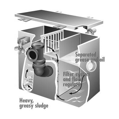
The exceptionally high efficiency of the Rockford Separator in retaining foreign waste matter in the unit is made possible by its design for maximum water travel through the separator without turbulence and by the filtering action of its screens.
Note course of water travel in cut-open view. Arrows designate course from inlet, under and through separator screen and flow-regulator filter screen, to outlet. There is no straight in-and-out travel from inlet to outlet. Note also separation and retention, through gravity action, of lighter-than-water matter. The inlet closes when the separator’s holding capacity is reached if the unit has been properly sized, installed correctly, and short circuiting devices and methods are not used.
A Rockford Separator has a built-in flow control; it needs no external flow control.
TRAVEL OF WASTE WATER
Although it has the outward appearance of a straightthrough unit, there is no straight in-and-out travel of waste water from inlet to outlet, incorporating Rockford Separator standard features in maintaining minimum turbulence, internal flow regulation through its filter screens, and maximum length of water travel.
CONSTRUCTION
The Rockford Separator is built of all-welded heavy gauge steel for maximum structural strength and durability.
Gasketed cover is fastened to unit body by bolt assemblies, cross-tightened by hand to assure leakproof and airtight fit.
The M units (straight through) have a non-removable separating screen and one filter screen to regulate flow and filter waste water, making outside flow control or retarder unnecessary. The filter screen lifts out for easy cleaning of separator.
The L and R units have a removable separating screen (U-shaped) and filter screen (V-shaped) that lift out for easy cleaning of the unit. The slotted wall of the separator screen faces away from the inlet. The outlet is separated from main body of the unit (accepted by all plumbing codes). This provides an outside visible trap seal which protects against entry of sewer air. Outlet may be vented off vertical rise on tee or off horizontal run from unit. Standard tapped inlet and outlet are furnished.
COR-TEN® INFORMATION
Cor-Ten® high-strength, low carbon steel with its high strength and outstanding resistance to atmospheric corrosion is available where maintenance cost savings are prime considerations. Even in an unpainted condition, Cor-Ten® has a tightly adherent oxide surface which stops further oxidation. Painted or coated, this characteristic is further enhanced. The reliability and strength of this material has been proven in many applications, such as railroad cars, bridges and two of the tallest buildings in the world: the John Hancock Building and the Sears Tower in Chicago.
LOCATION OF SEPARATOR
When deciding on the location for the separator, be sure there is headroom to lift out the screens for cleaning; otherwise use flush-with-floor model. Locate separator as close to fixture as possible. Venting is necessary on outlet leg to prevent siphonage. On larger models with internal rear vent, the separator body must be vented. Comply with local code requirements on all installations of separators.