Helicopter port fuel interceptor shall be Rockford Interceptors as manufactured by Rockford Separators, Rockford, Illinois and as noted on plans.
SPECIFICATIONS
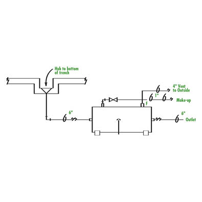
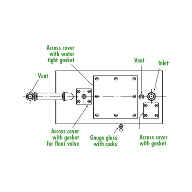
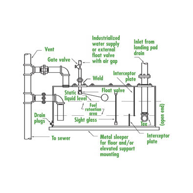
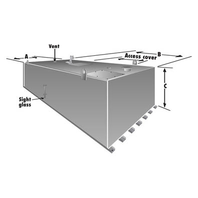
Furnish Rockford Model RHS-____ Helicopter Port Fuel Interceptor constructed entirely from high-strength, low-alloy plate 1/4″ ASTM-A242, 6″ flanged inlet and outlet, with outlet vent connection, 4″ internal vent connections, gasketed access covers secured with stainless steel bolts, 2″ fuel drain connection, 1″ fresh water supply connection with gate valve, back flow preventer, automatic water level float valve, external sight glass water level indicator with drain cocks, 2″ interceptor drain plugs, channel support rails and body corner lifting lugs. Body of interceptor shall be welded inside and outside, water tested, thoroughly air dried, coated inside and outside with OPEX® Shop Coat coatings.
OPTIONAL EQUIPMENT
Elevated support frame or elevated support frame with walkway.
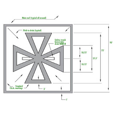
RECOMMENDED HELIPORT MARKING • FEDERAL AVIATION ADMINISTRATION AC-150/3390-1A
The standard pattern marking is dimensioned for a pad size of 90 feet or more. For pattern sizes other than 75 feet, scale dimensions proportionately. The touchdown area should be clearly defined by a solid or segmented border at least one foot wide. On surfaces of light color, markings should be outlined in black to increase their visibility.
- Consult the local municipal, county or state authority to determine who has jurisdiction.
- Consult the proper administrative authorities to ascertain any special requirements or restrictions.
– Building Department – Plumbing Division
– Federal Aviation Agency – F.A.A. Local Office
– Health Department – In some states
– Sanitary District – Industrial Waste Ordinance
– Sewer Department – Industrial Waste Control
– Fire Department – Fire Prevention Bureau
– Zoning Department – Restrictions or Variance
With the use of helicopters for short flights and the increasing use of rooftops and other elevated structures for landing facilities, the possibilities for emergency situations have also increased. The protection of life and property is best accomplished through preventive means. Mechanical failures in aircraft can easily result in crash landings. Fuel spillage on such facilities presents a fire hazard to persons in and near these facilities. The resultant damage to the building or structure itself must be taken into account. Prevention of a potential catastrophe is paramount.
These specifications contain guidance material which may be used verbatim by specifying engineers for possible procurement purposes.
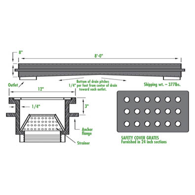
SAFETY TRENCH DRAIN
The prevention of fuel and/or water ponding on the landing pad is accomplished by means of a large trench type drain covered by an inlet grate with sufficiently large enough openings to allow fast drainage.
NON-SPARKING INLET GRATES
The cover grates shall be of a non-sparking metallic material and shall be loosely set to permit ready access to the interior of the drain.
JOB SPECIFICATIONS
Helicopter Pad Safety Drain shall be Rockford Model RHD-8 as manufactured by Rockford Sanitary Systems, Rockford, IL as shown on plans.
DRAIN SPECIFICATIONS
Furnish Rockford Model RHD-8 Helicopter Pad Safety Drain constructed of ASTM-A242 high-strength, low-alloy plate with non-sparking safety cover grates of AA-7075-T6 Fed. Spec. QQ-A-250/12 material with circular grate openings. Two 4″ threaded double outlet connections.
OPTIONAL EQUIPMENT
Flashing flange and clamping ring.
TYPICAL INSTALLATION
Install unit within 10 feet of the landing pad. If unit is installed at greater distances from the pad, the unit must be sized accordingly.
DESIGN CONSIDERATIONS
Careful consideration must be given to all aspects of design and installation of the system. It shall be in accordance with the best engineering practices and provide ready accessibility for ease in operation and maintenance. Refer to storage tank section – Page.51
MATERIALS
All materials specified shall be of the best quality used for the purpose intended. They shall be free from defects and imperfections that might adversely affect the serviceability of the completed installation.
PROTECTION
Provisions shall be provided to protect all portions of the installation subject to freezing. Conversely, all portions of the installation holding fuel shall be protected from thermal expansion due to the direct rays of the sun.
SIZING OF FUEL SEPARATOR
Determine the manufacturer and model of helicopter(s) that will use the pad. The fuel tank capacity of the largest helicopter using the pad will determine the model fuel separator that is to be installed. Select a fuel separator with a fuel retention capacity equal to or greater than the fuel tank capacity of the largest helicopter.
MINIMUM SIZE FUEL SEPARATOR
The water seal capacity shall not be less than 18cu. ft. with a surface area not more than 22 sq. ft. and a water seal depth of not less than 16″ nor more than 18″.
NOTE
These are helicopter port fuel interceptors.
LARGER UNITS AVAILABLE
| Model | Water Depth | Tapped Inlet and Outlet (in.) | Water Seal (gal.) | Water Seal (cu. ft.) | Width A (in.) | Length B (in.) | Height C (in.) | Fuel Retention Capacity (gal.) | Surface Area (sq.ft.) | Ullage (cu.ft.) | Shipping Weight (lb.) | Operating Weight (lb.) | CAD Specification Drawing |
|---|---|---|---|---|---|---|---|---|---|---|---|---|---|
| RHS-10 | 1'5" | 6 | 135 | 18 | 3'0" | 7'6" | 4'0" | 35 | 22.46 | 52.65 | 1650 | 4000 | |
| RHS-20 | 1'5" | 6 | 175 | 23.3 | 4'0" | 10'6" | 4'0" | 65 | 41.77 | 56.28 | 2975 | 6300 | |
| RHS-30 | 1'5" | 6 | 200 | 26.6 | 5'3" | 11'0" | 4'0" | 90 | 57.75 | 135.14 | 3524 | 8650 | |
| RHS-40 | 1'5" | 6 | 300 | 40 | 7'8" | 16'0" | 4'0" | 195 | 125.31 | 279.77 | 5000 | 15000 | |
| RHS-50 | 1'5" | 6 | 350 | 46.6 | 8'0" | 17'9" | 4'0" | 220 | 141.17 | 332.28 | 5600 | 19000 | |
| RHS-60 | 1'5" | 6 | 395 | 52.48 | 8'0" | 20'0" | 4'0" | 250 | 160 | 400 | 6220 | 21360 |