Drains shall be Rockford Combination Separator-Drains, as manufactured by Rockford Separators, Inc., Rockford, Illinois, and as noted on plans.
SEPARATOR-DRAIN SPECIFICATIONS
Furnish ______Rockford Model SD-______all-welded steel combination separator-drains, ______” (tapped) (hubbed) outlet with outlet vent connection, ______” internal rear vent connection, visible double-wall outside trap seal, (easily removable) (tamper-proof) non-breakable inlet grate of (steel) (polished brass) with slotted inlet grate openings, grate suitable for ______ (specify pedestrian traffic or reinforced for heavy vehicular traffic), removable sediment and mud pan, separator screen, and filter screen, OPEX® Shop Coat coating inside, bituminous coating outside.
OPTIONAL FEATURES:
Inlet grate of stainless steel, concrete anchor flange with or without non-puncturing clamping ring, weep holes. Epoxy coated. Circular inlet grate openings. Integral extensions available.
NOTES FOR GRATES:
All standard grates are made with ASTM A242 material. A) Stock grates rated at 500# wheel load.B) Light traffic rated at 1000# wheel load (H-10). C) Heavy traffic rated at 16,000# wheel load (H-20).
NOTE
HOW TO ORDER
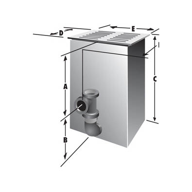
When an extension is needed to meet deep roughing-in of the outlet, select the separator drain of the right size and capacity from the table. Then determine required dimension A from center of outlet to top of inlet grate.
Dimension A is variable and can be specified to a fraction of an inch; integral extensions in 6-inch increments indicate price breaks. Dimension A plus dimension B is the overall height of separator drain C.
* Smaller outlets available.
+ 3/8″ x 3″ slots (optional circular openings not available on SD-18 – 3/8″ x 3″ slots only).
• 6″ & larger – companion flange connection.