GENERAL INFORMATION
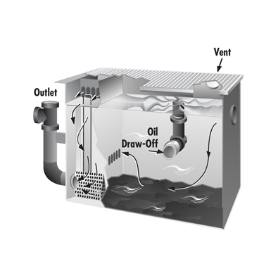
Our simple design is a perfect application of the principle of nature’s own law of gravity in separating lighter-than water wastes from heavier-than-water matter. These light-density substances, as well as oily, greasy sludge or solids, are retained in the Rockford Separator. Note the course of water travel in cut-open view. The arrows designate the course from the inlet through the first separating screen, upward and through the second separating screen, downward through the filter and flow regulator screen to the outlet, and upward to the drainage line. There is no straight in-and-out travel from the inlet to the outlet of the separator. For continuous or severe operation, consult our Engineering Department.
APPLICATIONS
Rockford Oil Separators are designed to receive, directly from plant equipment or floor drains, various kinds of oils, gasoline, kerosene, naphtha, benzene, other volatile liquid waste, and sludge. They retain this harmful waste matter and prevent its entry into the drainage system, providing triple advantages.
ADVANTAGES
The safe retention of this flammable material reduces:
- The hazards of fire and explosions inside the building
- Pollution of our soil and waterways caused by the indiscriminate disposal of waste material
- Loss of a salable or reusable by-product.
CONSTRUCTION
The separator is built of all-welded heavy-duty steel plate for maximum strength and durability. Both the interior and exterior are coated to resist acid corrosion. These units have removable covers for on-the-floor, partially recessed or flush-with-floor installation, suitable for pedestrian traffic or reinforced for heavy traffic. The cover is secured to the body with recessed stainless steel bolts and includes an extra-heavy leakproof gasket. Separating screens and a flow-regulator filter screen regulate flow and filter waste water, making outside flow control or retarder unnecessary. An extra-large inlet compartment has adjustable oil draw-off. The outlet is separated from the main body of the unit, meeting all plumbing code requirements of an outside visible trap seal. Independent internal vent connection on the inlet compartment dissipates excessive fumes and vapors from evaporating gases and volatile liquids. The outlet of the separator is vented to prevent siphoning of its contents into the drainage system. All units are available in double-wall construction with leak detection if specified.
COR-TEN® INFORMATION
Cor-Ten® high-strength, low carbon steel with its high strength and outstanding resistance to atmospheric corrosion is available where maintenance cost savings are prime considerations. Even in an unpainted condition, Cor-Ten® has a tightly adherent oxide surface which stops further oxidation. Painted or coated, this characteristic is further enhanced. The reliability and strength of this material has been proven in many applications, such as railroad cars, bridges and two of the tallest buildings in the world: the John Hancock Building and the Sears Tower in Chicago.
METHOD OF OPERATION
The basic requirement for efficient retention of non-soluble oil or other volatile liquid wastes is the absence of turbulence in the waste water movement. This is accomplished in the Rockford Separator by its design for maximum water travel without agitation and by the filtering action of its screens. The combination of two separating screens and a flow-regulator filter screen reduces the turbulence to allow proper separation, and prevents the evacuation of solids into the drainage system. The absence of a solids-evacuating channel is additional proof of the non-turbulent flow through the separator.
SAFETY FEATURES
Visible double-wall outside trap seal with vent connection prevents siphoning. Separate internal vent connection keeps pressure from building up inside the unit and from forcing contents into the drainage system. The independent vent also releases any fumes which may build up inside the unit. The wet inlet design prevents the entry of sewer air into the premises.
ENGINEERING SERVICE
Where individual problems or large projects require special applications, the assistance of our Engineering Department is recommended.
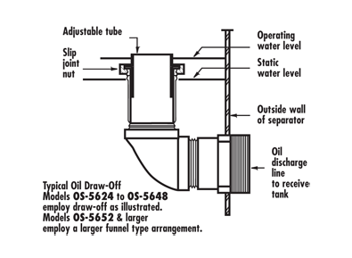
OIL DRAW-OFF
The oil draw-off funnel is adjustable to the gravity height of oil and gallon-per-minute flow. It leads into the oil discharge pipe, from which a suitable disposal of oil can be made in the most economical way. After the separator is installed, establish the operating water level by running water through the separator at the maximum flow rate expected. Adjust the vertical draw-off pipe 1/8″ to 1/4″ above the water line. Periodic checking of this level after the separator is in operation will ensure the proper functioning of the oil draw-off. If draw-off oil contains any water, raise the vertical draw-off pipe until only oil flows from the separator.
INTERMITTENT FLOW OIL SEPARATORS
The maximum amount of waste water containing non-soluble oil that can be discharged through any listed separator is two (2) times the stated flow rate in g.p.m. For example, a separator rated at 50 g.p.m. may only have 100 gallons discharged through it in a one-hour time period. This is usually accomplished by a batch dumping process. However, 100 gallons may be discharged continuously if the flow rate is monitored at the rate of 1.66 g.p.m.
COALESCING PACK (OPTIONAL FEATURE)
Removable polypropylene coalescing pack within a stainless steel framework is used to separate droplets of oil too minute to be removed by separation alone.
FILTER MEDIUM (OPTIONAL FEATURE)
Some oil-laden wastes carry with them small particles of suspended matter. For such installations, we recommend the OS Series separator be ordered with a filter medium. This will keep the tiny particles of suspended matter with attached oil globules from passing into the drainage line. Replacement filter screen with factory-installed filter medium is available as a replacement part.
Sizing for Typical Code Regulations Vehicle Servicing
When an oil separator is installed in an automobile, truck, bus, or tractor garage, in a service station or in a repair shop with facilities for motor or transmission overhauling, it must have a minimum static water depth of 24 inches below the invert of the separator outlet and a minimum static water capacity of 6 cubic feet. This regulation applies to facilities where not more than three vehicles are serviced. For each additional vehicle up to and including ten, 1 cubic foot of static capacity shall be added. For each vehicle over ten, an additional 0.25 cubic foot shall be added.
VEHICLE STORAGE
In motor vehicle storage facilities, a combination separator-drain shall be installed with a static water level of 1 gallon for every 100 square feet of area to be drained.
VEHICLE STORAGE AND SERVICING
Where motor vehicles are serviced and stored, an oil separator shall be installed with a static water capacity of 1 cubic foot for every 100 square feet of area to be drained. The oil separator shall have a minimum static water level of 6 cubic feet. Check local codes for specific requirements.
MECHANICAL CAR WASHING
In facilities designed especially for mechanical washing of motor vehicles, a sand and gravel separator shall be installed to receive the waste water from all washing facilities. A minimum static water level of 2.5 feet and a minimum static water capacity of 50 cubic feet shall be maintained.
Where motor cleaning services are rendered at mechanical car washing facilities, an oil separator shall be installed in that section of the drainage system which receives waste water from this operation.
MANUAL CAR WASHING
In a one-car washing facility, a combination separator-drain shall be installed with a minimum static water capacity of 30 gallons.
MANUAL CAR WASHING
CONTINUOUS FLOW DESIGN CRITERIA FORMULAE
ACTUAL JOB INSPECTION AND RECOMMENDATION
Upon inspection of your plant and testing of the waste oil sample received, we submit a report similar to the following for your consideration.
The following information was given to us:
- Water Consumption: 3,000,000 gallons per month
- Work Day: 24 hours
- Work Week: 6-day week
- Oil Consumed: 600 gallons per month
From the above information we obtained these figures as averages:
- Average Work Month: 25.5 days
- Flow Rate Per 24 Hour Period: 117,645 gallons
- Flow Rate Per Hour: 4,901 gallons
- Flow Rate Per Minute: 81.6 gallons, or 10.88cfm
Based upon the information received from the local sanitary district office, 200 ppm of oil is being discharged into the sewer. This totals out to 589 gallons per month. This concurs with the figure of 600 gallons per month that is purchased and consumed in your operations (589 gallons vs. 600 gallons).
DESIGN CRITERIA
Research and experimental work have led to the adoption of fundamental principles which provide mathematical bases for the determination of separator size and shape. These principles have been applied, and the results are separators demonstrating highly effective performance.
It must be noted that the design and shape of the separator depend upon the character and quantity of the oily water to be separated. Even a properly sized separator is limited to the separation of oils and solids which are susceptible to gravity separation. It must also be noted that modifications, and possible refinements to this design can result in separators with improvements and merits.
The following design criteria is based upon a mathematical formula resulting from research done, and upon which Rockford Separators base their design.
The design of a rectangular oil separator is based on three relationships:
- A minimum horizontal area
- A minimum vertical cross-sectional area
- A minimum ratio of depth to width of 0.3 (0.5 maximum).
The design of this separator was calculated using varying temperatures of waste water from 70°F to 100°F. We are presenting design information based upon a temperature of 100°F, which in our estimation, is more likely to be the average temperature.